A finished sheet metal part can look fairly simple. What isn’t always obvious is how many decisions and manufacturing steps went into producing it.
Before a flat sheet of metal becomes a bracket, panel, enclosure, frame, or finished assembly, it may go through cutting, forming, welding, grinding, finishing, inspection, and assembly. Each step affects the next, which is why the sheet metal fabrication process needs to be considered as a complete manufacturing sequence rather than a collection of separate operations.
For OEMs and manufacturers buying fabricated parts, understanding that process can also make it easier to design parts for production, communicate requirements, and avoid unnecessary cost or rework.
Here’s a practical look at how a typical sheet metal fabrication project moves from a drawing to a finished product.
It starts before the first sheet is cut
Fabrication begins with the part requirements.
A manufacturer may receive a 3D model, engineering drawing, CAD file, specifications, or some combination of these. Before production starts, the fabrication team needs to understand what is being made and what matters most about the finished part.
That includes details such as:
- Material type and thickness
- Overall dimensions
- Critical tolerances
- Hole and feature locations
- Bend locations and angles
- Weld requirements
- Surface and cosmetic requirements
- Hardware or inserts
- Finishing requirements
- Inspection requirements
- Production quantity
This upfront review matters because fabrication processes are connected.
A bend location can affect where a hole should be cut. A weld can introduce heat and distortion. A cosmetic surface may need to be protected throughout production. A tight tolerance that looks reasonable on a drawing may require a different manufacturing approach once the complete part is considered.
Finding those issues before production is usually much easier than discovering them after parts have already been cut.
Material selection and preparation
Once the requirements are established, the appropriate sheet material can be selected.
Common materials used in sheet metal fabrication include carbon steel, stainless steel, galvanized steel, and aluminum. The right choice depends on the application, environment, strength requirements, weight, appearance, and any finishing that will be applied later.
Material thickness matters as well.
A heavier gauge may provide additional strength, but it also changes the way the material cuts and forms. In some designs, bends, flanges, ribs, or other formed features can provide the required rigidity without simply increasing material thickness.
Material selection should therefore be considered alongside the design of the part rather than treated as an independent decision.
Cutting the flat pattern
For many fabricated parts, the first major production operation is cutting.
The goal is to create the flat profile of the part along with the holes, slots, openings, and other features required before forming.
Depending on the job, different cutting processes may be appropriate. Factors such as material, thickness, geometry, tolerance requirements, production volume, and edge requirements all influence that decision.
Laser cutting is commonly used for sheet metal parts because it can produce complex profiles and repeatable features directly from programmed geometry.
A laser can cut:
- Outside profiles
- Mounting holes
- Slots
- Ventilation patterns
- Cable openings
- Tabs
- Notches
- Other internal features
Accuracy at this stage is important because those features often need to line up with bends, hardware, mating components, or other parts later in the assembly.
For more information about HFI’s cutting capabilities, visit the Cutting section of the HFI website.
Bending and forming
Once a flat pattern has been cut, parts that require three-dimensional geometry move into forming.
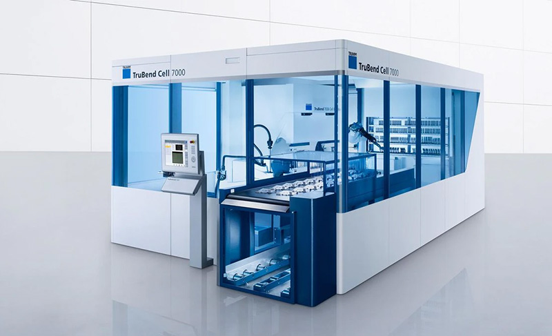
A CNC press brake is commonly used to create bends, flanges, channels, brackets, panels, and other formed features.
This sounds straightforward, but sheet metal does not behave like a piece of paper.
Material type, thickness, bend radius, tooling, grain direction, and the geometry of the part can all affect the result. The fabrication team also has to account for how the material changes as it is formed so that the finished dimensions match the drawing.
The order of the bends matters too.
A part with several bends may need to be formed in a particular sequence so that an earlier bend does not interfere with the tooling required for a later one.
Good design can make this process considerably easier. Providing adequate clearance around bends and considering how the part will physically fit into the press brake can reduce unnecessary complexity.
You can learn more about HFI’s forming capabilities on the Bending page.
Adding hardware and inserts
Some sheet metal components require more than the formed metal itself.
Threaded inserts, studs, nuts, standoffs, and other hardware may be installed to provide attachment points for equipment or mating components.
Where that hardware is located can affect earlier fabrication operations.
For example, an insert positioned too close to a bend may interfere with forming or require it to be installed later in the manufacturing sequence. Hardware also needs to be positioned accurately so that components fit properly during final assembly.
These are small details on a drawing, but they can have a significant effect on how efficiently a part moves through production.
Welding and joining
Many fabricated products consist of multiple pieces that need to be joined.
Depending on the material, design, and production requirements, welding may involve MIG, TIG, robotic welding, spot welding, or other joining processes.
The purpose isn’t simply to attach two pieces of metal. The weld needs to provide the required strength while maintaining the dimensions and appearance of the finished assembly.
Heat is an important consideration.
Welding introduces heat into the material, and that heat can cause distortion. Weld sequence, fixturing, joint design, and the amount of welding specified can all influence how well an assembly holds its intended dimensions.
For repeat production, fixtures can also help maintain consistent positioning from one assembly to the next.
Grinding and surface preparation
After welding, some parts require additional work before they are ready for finishing.
Grinding may be used to remove weld buildup, smooth joints, deburr edges, or prepare a surface for its final appearance.
The amount of grinding required depends heavily on the application.
A structural component hidden inside a larger assembly may have very different requirements from an exposed stainless steel panel where appearance is important.
This is why drawings should clearly identify cosmetic surfaces and finish expectations. Terms such as “smooth” can mean different things to different people. The more clearly the desired result is defined, the easier it is for the fabricator to build the appropriate process around it.
Finishing
Finishing can serve both functional and cosmetic purposes.
Depending on the part and its application, the final finish may provide corrosion resistance, improve appearance, prepare the surface for use in a particular environment, or simply create a consistent look across an assembly.
The finish also needs to be considered earlier than many buyers expect.
A coating adds thickness. Cosmetic surfaces may need protection during fabrication. Areas used for grounding or electrical contact may need different treatment. Certain assemblies may also be easier to finish before final assembly rather than afterward.
Treating finishing as part of the manufacturing plan—not simply the last operation—can prevent problems late in production.
Assembly and kitting
Some fabrication projects end with an individual component. Others continue into assembly.
Fabricated parts may be combined with hardware, brackets, purchased components, or other pieces before being shipped to the customer.
Assembly and kitting can be particularly useful for OEMs purchasing groups of related parts.
Instead of receiving several loose components from different operations and assembling everything internally, the customer may receive a completed subassembly or organized kit that is ready for the next stage of production.
The right approach depends on the product and how it fits into the customer’s manufacturing process.
Inspection throughout the process
Quality isn’t something that can simply be checked into a part at the very end.
Inspection can take place at several points during the sheet metal fabrication process.
The exact inspection plan depends on the drawing, tolerances, customer requirements, and complexity of the part. Critical dimensions may be checked after cutting or forming, while completed assemblies may require additional inspection before shipment.
For a new part or production program, first article inspection can provide an opportunity to verify the initial manufactured part against the engineering requirements before moving further into production.
That can be particularly valuable when a component will be produced repeatedly.
Why the order of operations matters
One of the most important aspects of sheet metal fabrication is something customers rarely see: deciding when each operation should happen.
A hole might need to be cut before bending because it becomes inaccessible afterward. Hardware may need to be installed after forming. Welding may need to happen before a cosmetic finishing operation. An assembly may require inspection before another component blocks access to a critical dimension.
Changing the sequence can sometimes turn a difficult part into a straightforward one.
That’s why experienced fabrication teams look beyond individual processes. They consider how the part will move through the entire shop.
Designing with the fabrication process in mind
A part that works perfectly in CAD isn’t necessarily easy or economical to manufacture.
Small design decisions can affect production considerably.
Hole locations near bends, unnecessarily tight tolerances, difficult weld access, excessive numbers of unique components, or features requiring additional setups can all add manufacturing time without necessarily improving the finished product.
That doesn’t mean every part should be redesigned around the easiest manufacturing process. Some requirements simply have to be met.
The goal is to understand which features are important to the function of the product and which ones can be adjusted to make production more efficient.
Getting the fabricator involved early can help identify those opportunities before the design is locked in.
The bottom line
The sheet metal fabrication process is more than cutting a piece of metal and bending it into shape.
A finished component may pass through programming, cutting, forming, hardware insertion, welding, grinding, finishing, assembly, and inspection before it reaches the customer.
More importantly, those operations aren’t independent. Decisions made at one stage can affect nearly every stage that follows.
For OEMs and manufacturers, working with a fabricator that can look at the complete production process can help identify potential issues earlier and create a more repeatable path from drawing to finished part.
HFI Manufacturing provides sheet metal fabrication services including cutting, CNC forming, welding, grinding and finishing, assembly, and related manufacturing support. HFI works with OEMs across a range of industries to manufacture parts and assemblies to customer drawings and specifications.
Talk to HFI about your next sheet metal fabrication project or call (630) 293-9300 to discuss your requirements.